
Communicating with your MicroFramework Application over USB
Version 3.0 of the MicroFramework SDK (finally!) supports configuring USB for other functions than just debug. This means you can now use USB as a communications medium for your applications. Microsoft ships a sample that shows one of those possibilities: Transforming your device into a mouse. In this blog post I'll show a more useful solution: How to setup a MicroFramework device so you can send and receive data over USB to and from the device.
Independent hardware vendors (IHVs) who manufacture USB devices must typically provide a way for applications to access the device’s features. Historically, this has meant using the Windows® Driver Model (WDM) to implement a function driver for the device and installing the driver in the device stack. However, drivers require a significant development effort, and some devices are simple enough that they do not require the full support of a custom function driver.
The USB functionality we'll be developing will be simple, so writing a full function driver will be overkill. Luckily Microsoft introduced the user-mode driver framework (UMDF) and part of this framework is WinUSB. WinUSB was developed concurrently with the Windows Driver Foundation (WDF) and is available for Windows XP and later versions of Windows. It includes a kernel-mode driver, WinUsb.sys, which is an integral part of the WDF-UMDF support for USB drivers. For USB devices that are accessed by only a single application, you can often install WinUsb.sys as the device’s function driver instead of implementing a custom driver. The application can then configure the device and access its endpoints by using the WinUSB API, and that's exactly what I'll do in this example!
WinUSB consists of two primary components:
- WinUsb.sys is a kernel-mode driver that can be installed as either a filter or function driver, above the protocol drivers in a USB device’s kernel-mode device stack.
- WinUsb.dll is a user-mode DLL that exposes the WinUSB API. Applications can use this API to communicate with WinUsb.sys when it is installed as a device’s function driver.
For devices that do not require a custom function driver, WinUsb.sys can be installed in the device’s kernel-mode stack as the function driver. User-mode processes can then communicate with WinUsb.sys through a set of device I/O control requests. The WinUSB API, exposed by WinUSB.dll, simplifies this communication process. Instead of constructing device I/O control requests to perform standard USB operations such as configuring the device, sending control requests, and transferring data to or from the device, applications call equivalent WinUSB API functions. Internally, WinUsb.dll uses the data that the application passes to the WinUSB function to construct the appropriate device I/O control request and sends the request to WinUsb.sys for processing. When the request is complete, the WinUSB function passes any information returned by WinUsb.sys such as data from a read request—back to the calling process.
Using the WinUSB API to communicate with a device is much simpler than implementing a driver, but has some corresponding limitations:
- The WinUSB API allows only one application at a time to communicate with the device. If more than one application must be able to communicate concurrently with a device, you must implement a function driver.
- The WinUSB API does not support streaming data to or from isochronous endpoints. Isochronous transfers require a kernel-mode function driver.
- The WinUSB API does not support devices that already have kernel-mode support. Examples of such devices include modems and network adaptors, which are supported by the telephony API (TAPI) and NDIS, respectively.
- For multifunction devices, you can use the device’s INF to specify either an in-box kernel-mode driver or WinUsb.sys for each USB function separately. However, you can specify only one of these options for a particular function, not both.
WinUSB is natively supported on all Windows Vista SKU's and is supported on all SKU's of the 32 bit versions of Windows XP SP2 and later service packs. WinUSB is not native to Windows XP; it must be installed with the WinUSB co-installer.
The WinUSB co-installer package can be found in the Windows Driver Kit under the WinDDK\BuildNumber\Redist\Winusb folder. The DLLs are signed and can be redistributed by IHVs. So if you want to develop an application that talks to your MicroFramework device over USB under XP, you'll have to install the WinDDK. After you've completed your development and are ready to ship your device your customers of course don't have to install the WinDDK to use your application because you'll ship your device with an installer that includes the redistributable co-installer package.
Read "How to Get the WDK and the WLK" to obtain the latest WDK version.
Before your application can use the WinUSB API to communicate with your device, you must install WinUsb.sys as the device’s function driver. To do so, you have to create a package that includes:
- The WinUSB co installer, which installs WinUSB on the target system, if necessary. The WDK includes two versions of the co-installer, one for x86 systems and one for x64 systems. They are both named WinUSBCoInstaller.dll and are located in the WinDDK\BuildNumber\redist\winusb folder.
- The Kernel Mode Driver Framework (KMDF) co installer, which installs the correct version of KMDF on the target system, if necessary. This co-installer is required because WinUsb.sys depends on KMDF. The x86 and x64 versions of WdfCoInstaller01005.dll are included with the WDK under the WinDDK\BuildNumber\redist\wdf folder (but you need WDK version 6001.18002 or higher).
- An INF that installs WinUsb.sys as the device’s function driver.
- A signed catalog file for the package. This file is required to install WinUSB on x64 versions of Windows Vista. For more information on how to create and test signed catalog files, see "Kernel-Mode Code Signing Walkthrough". Note that this document states that Inf2Cat is not currently part of the WDK tools, but in fact it is (you can find it in \WinDDK\BuildNumber\bin\SelfSign).
Before we can create the INF, let's define what we want our MicroFramework device to do, and develop the device side code!
In this example we want to keep it as simple as possible; all we want is two-way communication with our device. The best option for this is to create 2 bulk endpoints; one for reading and one for writing data. I'll be using the DeviceSolutions TahoeII board to develop the application on.
[Note: Download all code below]
Let's start coding!
- Start Visual Studio 2008
I'm assuming you have Visual Studio 2008 with SP1, the .NET MicroFramework SDK v3.0 and the TahoeII SDK v3.0 installed. - Create a new MicroFramework Console Application
- First let's add the needed references. Right click on your project in the solution explorer and select "Add reference...". Now add the following references:
- Microsoft.SPOT.Hardware.Usb
- Open program.cs and add the following to the top of the file:
using Microsoft.SPOT.Hardware.UsbClient; - Add the following constants to class Program:
private const int WRITE_EP = 1;
private const int READ_EP = 2;We use these constants so we can easily change the used endpoints if needed.
- Delete the standard
Debug.Printline from the function Main() - Now we add code to function Main() to detect the number of USB Controllers supported by the hardware:
// See if the hardware supports USB
UsbController[] controllers = UsbController.GetControllers();// Bail out if USB is not supported on this hardware!
if (0 == controllers.Length)
{
Debug.Print("USB is not supported on this hardware!");
return;
} - At this moment the .NET MicroFramework 3.0 does not support changing the USB configuration on the fly so using USB for application communication and Visual Studio Debugging is not possible when configuring USB from C# code running on the device. If you update the device's USB descriptors through XML using MFDeploy it is possible to debug and communicate at the same time (over multiple USB interfaces descriptors that is! More about that in a follow up post about CDC).
// Find a free USB controller
UsbController usbController = null;
foreach (UsbController controller in controllers)
{
if (UsbController.PortState.Stopped == controller.Status)
{
usbController = controller;
break;
}
}// If no free USB controller
if (null == usbController)
{
Debug.Print("All available USB controllers already in use. Set the device to use Ethernet or Serial debugging.");
return;
}Setting the TahoeII to use Ethernet or serial debugging is easy; just hold SW4 while resetting the device for debugging over Ethernet, or hold SW2 for debugging over serial. If you set it to debug over Ethernet then don't forget to configure the TahoeII's Ethernet settings using MFDeploy (see "Configuring Ethernet on the Tahoe-II" in the TahoeII SDK documentation -> press F1 in Visual Studio)
- If we found a free USB controller we can now start to configure that controller. We'll put the configuration code in a separate function to keep it all together. Add the following function to the Program class:
-
private static bool ConfigureUSBController(UsbController usbController)
-
{
-
bool bRet = false;
-
-
// Create the device descriptor
-
Configuration.DeviceDescriptor device = new Configuration.DeviceDescriptor(0xDEAD, 0x0001, 0x0100);
-
device.bcdUSB = 0x110;
-
device.bDeviceClass = 0xFF; // Vendor defined class
-
device.bDeviceSubClass = 0xFF; // Vendor defined subclass
-
device.bDeviceProtocol = 0;
-
device.bMaxPacketSize0 = 8; // Maximum packet size of EP0
-
device.iManufacturer = 1; // String #1 is manufacturer name (see string descriptors below)
-
device.iProduct = 2; // String #2 is product name
-
device.iSerialNumber = 3; // String #3 is the serial number
-
-
// Create the endpoints
-
Configuration.Endpoint writeEP = new Configuration.Endpoint(WRITE_EP, Configuration.Endpoint.ATTRIB_Bulk | Configuration.Endpoint.ATTRIB_Write);
-
writeEP.wMaxPacketSize = 64;
-
writeEP.bInterval = 0;
-
-
Configuration.Endpoint readEP = new Configuration.Endpoint(READ_EP, Configuration.Endpoint.ATTRIB_Bulk | Configuration.Endpoint.ATTRIB_Read);
-
readEP.wMaxPacketSize = 64;
-
readEP.bInterval = 0;
-
-
Configuration.Endpoint[] usbEndpoints = new Configuration.Endpoint[] { writeEP, readEP };
-
-
// Set up the USB interface
-
Configuration.UsbInterface usbInterface = new Configuration.UsbInterface(0, usbEndpoints);
-
usbInterface.bInterfaceClass = 0xFF; // Vendor defined class
-
usbInterface.bInterfaceSubClass = 0xFF; // Vendor defined subclass
-
usbInterface.bInterfaceProtocol = 0;
-
-
// Create array of USB interfaces
-
Configuration.UsbInterface[] usbInterfaces = new Configuration.UsbInterface[] { usbInterface };
-
-
// Create configuration descriptor
-
Configuration.ConfigurationDescriptor config = new Configuration.ConfigurationDescriptor(180, usbInterfaces);
-
-
// Create the string descriptors
-
Configuration.StringDescriptor manufacturerName = new Configuration.StringDescriptor(1, "GuruCE");
-
Configuration.StringDescriptor productName = new Configuration.StringDescriptor(2, "MicroFramework WinUSB");
-
Configuration.StringDescriptor serialNumber = new Configuration.StringDescriptor(3, "0000-0000-0000-0001");
-
Configuration.StringDescriptor displayName = new Configuration.StringDescriptor(4, "MicroFramework WinUSB");
-
Configuration.StringDescriptor friendlyName = new Configuration.StringDescriptor(5, "NetMF_WinUSB");
-
-
// Create the final configuration
-
Configuration configuration = new Configuration();
-
configuration.descriptors = new Configuration.Descriptor[]
-
{
-
device,
-
config,
-
manufacturerName,
-
productName,
-
serialNumber,
-
displayName,
-
friendlyName
-
};
-
-
try
-
{
-
// Set the configuration
-
usbController.Configuration = configuration;
-
if (UsbController.ConfigError.ConfigOK != usbController.ConfigurationError)
-
throw new ArgumentException();
-
// If all ok, start the USB controller.
-
bRet = usbController.Start();
-
}
-
catch (ArgumentException)
-
{
-
Debug.Print("Can't configure USB controller, error " + usbController.ConfigurationError.ToString());
-
}
-
return bRet;
-
}
The MicroFramework SDK v3.0 shipped without documentation on the new USB classes, but an extra download updating the documentation fixes that.
Let's step through the code:
- Line 6-14: We start by creating the device descriptor. The constructor of the Configuration.DeviceDescriptor Class has the following signature:
public DeviceDescriptor(ushort Vendor, ushort Product, ushort DeviceVersion)Using parameter "Vendor" we supply the VID of the device. In this example I'm using a non-existing VID (0xDEAD), but in your final commercial device you'd have to use your own registered VID (check out http://usb.org for information on how to acquire a VID/PID). Note that in most countries using someone else's VID is considered theft and thus a criminal offense, not just a civil one. The parameter "Product" is used to supply the PID. In this case we'll just use a PID of 0x0001. The "DeviceVersion" parameter can be used to indicate device version and you are free to set this to anything you like (I set it to "1.0").
The next 4 lines set the USB version in bcdUSB (USB 1.1), the device class, subclass & protocol. We set these to indicate our device is a custom vendor defined class; it doesn't fit in one of the predefined USB classes. The MicroFramework firmware already sets up control endpoint 0 for us so all we have to do is supply the maximum packet size of EP0. Even though the maximum packet size for EP0 is 32 bytes (see the iMXS datasheet; the processor the Meridian module on the TahoeII board is using) the TahoeII firmware sets it up as 8 bytes, so we have to set this field to 8. The iManufacturer, iProduct and iSerialNumber fields are indexes pointing to strings (that are defined in lines 40 - 44). - Line 17-25: Here we create our two endpoints: EP1 BULK IN (which means data flows from device to host, so we'll call this WRITE) and EP2 BULK OUT (which means data flows from host to device so we'll call this READ). The class constructor:
public Endpoint(byte EndpointAddress, byte Attributes). The EndpointAddress indicates the physical endpoint number. The attributes indicate the type of transfer, the type of synchronization and the usage type for the endpoint.
After creating the two endpoints we store them in an array of endpoints so we can include them in the UsbInterface: - Line 28-34: The UsbInterface class constructor has the following signature:
public UsbInterface(byte InterfaceNumber, Microsoft.SPOT.Hardware.UsbClient.Configuration.Endpoint[] Endpoints)The parameter InterfaceNumber allows us to define multiple interfaces with a different set of endpoints. In this case I define only 1 interface with 2 endpoints in the array. We set the InterfaceClass and InterfaceSubClass again to "vendor defined" and we put our interface in an array so we can include them in the configuration descriptor:
- Line 37: The ConfigurationDescriptor class constructor has the following signature:
public ConfigurationDescriptor(ushort MaxPower_mA, Microsoft.SPOT.Hardware.UsbClient.Configuration.UsbInterface[] Interfaces)The parameter MaxPower_mA is used to set the maximum power in mA. The TahoeII draws an absolute maximum of 180 mA, so that's what we set. The 2nd parameter holds our interfaces.
- Line 40-44: Here we create our string descriptors that we point at in line 12 - 14.
- Line 46-57: After creating the various descriptors we can now put them all together in the Configuration class.
- Line 59-71: And finally we apply the configuration and start the USB controller.
-
- Now that we've finished that function, we can continue adding code to the end of the Main() function:
UsbStream usbStream = null;
try
{ // Configure the USB controller
if (ConfigureUSBController(usbController))
usbStream = usbController.CreateUsbStream(WRITE_EP, READ_EP);
else
throw new Exception();
}
catch (Exception)
{
Debug.Print("USB stream could not be created, error " + usbController.ConfigurationError.ToString());
return;
}The code above calls the ConfigureUSBController function we created before and creates the USB stream.
- All we want our program to do is echo back whatever our application running on the PC sends to it. Add the following function to the Program class:
static void USBLoop(UsbStream usbStream)
{
byte[] readData = new byte[100];
for (; ; )
{
int bytesRead = usbStream.Read(readData, 0, readData.Length);
if (bytesRead > 0)
{ // echo back!
usbStream.Write(readData, 0, bytesRead);
}
}
} - And finally we'll call this never ending loop by adding the following code to the end of the Main() function:
// Start our communication loop
USBLoop(usbStream);
usbStream.Close();Of course the usbStream.Close() function will never be reached in our case, but we could add code to return from the loop if "Quit" is received for instance...
- Now that our program is finished we have to set up the correct debug transport to the TahoeII. Before switching the TahoeII to Ethernet you'll have to configure the Ethernet settings using MFDeploy:
- Make sure the TahoeII is using USB as a debug transport by holding SW3 while resetting the TahoeII
- Now start MFDeploy and select "USB" from the Device dropdown. The TahoeII should immediately pop up (as "Meridian_XXXXXXXX"). Ping the device to make sure you can reach it.
- From the Target menu, click "Configuration" and select "Network".
- Configure the TahoeII to match your network (set a static IP and subnetmask within range of your PC's IP or enable DHCP if you have a DHCP server on your network)
- Now set the TahoeII to use TCP/IP as debug transport by holding SW4 while resetting the device.
If the TahoeII is setup for TCP/IP we have to setup Visual Studio 2008 to use TCP/IP as well: Right click on your project in the solution explorer, choose "Properties" and click on the ".NET Micro Framework" tab. Select "All Configurations" from the "Configuration" dropdown list, set "Transport" to "TCP/IP" and you should see the device's IP and MAC address appearing in the "Device" dropdown list. Select the correct one (if you have more than one TahoeII connected) and close this window.
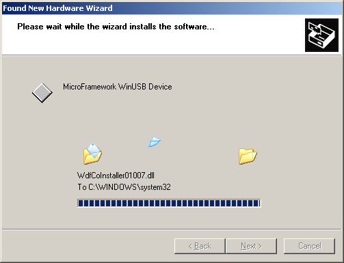
If all is well you can now press F5 to build and deploy the program. If you keep a close eye on your taskbar notification area you'll see the following notifications pop up:
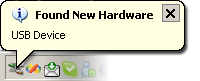

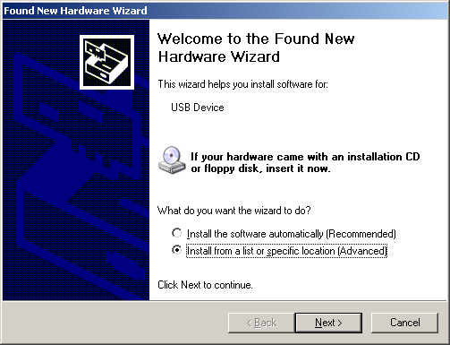
And after that XP will ask you for the driver:
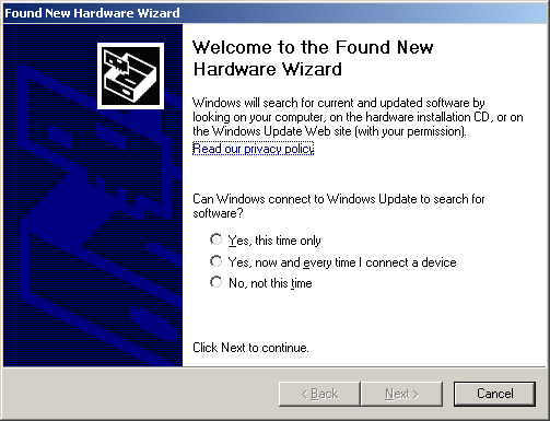
Since we'll be using WinUSB as the driver, all we need to do now is create the .inf file for our device. The document "How to Use WinUSB to Communicate with a USB Device" explains in detail how to do exactly that. If we modify the sample from that document according to the instructions we'll end up with an inf that looks like this:
Signature = "$Windows NT$"
Class = MicroFrameworkWinUSB
ClassGuid = {F80EAFB4-8422-446d-BC18-63B1BC21843E}
Provider = %ProviderName%
CatalogFile = MFWinUSB.cat
DriverVer = 05/30/2009,1.0.0.0
; ========== Manufacturer/Models sections ===========
[Manufacturer]
%ProviderName% = MicroFramework_WinUSB,NTx86,NTamd64,NTia64
[MicroFramework_WinUSB.NTx86]
%USB\MFWinUSB.DeviceDesc% = USB_Install, USB\VID_DEAD&PID_0001
[MicroFramework_WinUSB.NTamd64]
%USB\MFWinUSB.DeviceDesc% = USB_Install, USB\VID_DEAD&PID_0001
[MicroFramework_WinUSB.ntia64]
%USB\MFWinUSB.DeviceDesc% = USB_Install, USB\VID_DEAD&PID_0001
; =================== Installation ===================
;[0]
; If the class used in the Version section above is not a standard one
; (see http://msdn.microsoft.com/en-us/library/ms791134.aspx)
; then it must install information about the device class so it is displayed
; and processed correctly by various tools like the device manager, WMI, etc...
[ClassInstall32]
AddReg = MicroFrameworkWinUSB_addreg
[MicroFrameworkWinUSB_addreg]
HKR,,,,%ClassName%
HKR,,Icon,,"18"
;[1]
[USB_Install]
Include = WinUSB.inf
Needs = WinUSB.NT
;[2]
[USB_Install.Services]
Include = WinUSB.inf
AddService = WinUSB,0x00000002,WinUSB_ServiceInstall
;[3]
[WinUSB_ServiceInstall]
DisplayName = %WinUSB_SvcDesc%
ServiceType = 1
StartType = 3
ErrorControl = 1
ServiceBinary = %12%\WinUSB.sys
;[4]
[USB_Install.Wdf]
KmdfService = WinUSB, WinUSB_Install
[WinUSB_Install]
KmdfLibraryVersion = 1.7
;[5]
[USB_Install.HW]
AddReg = Dev_AddReg
[Dev_AddReg]
HKR,,DeviceInterfaceGUIDs,0x10000,"{77C99034-2428-424a-8130-DC481841429B}"
;[6]
[USB_Install.CoInstallers]
AddReg = CoInstallers_AddReg
CopyFiles = CoInstallers_CopyFiles
[CoInstallers_AddReg]
HKR,,CoInstallers32,0x00010000,"WinUSBCoInstaller.dll","WdfCoInstaller01007.dll,WdfCoInstaller"
[CoInstallers_CopyFiles]
WinUSBCoInstaller.dll
WdfCoInstaller01007.dll
[DestinationDirs]
CoInstallers_CopyFiles = 11
; ================= Source Media Section =====================
;[7]
[SourceDisksNames]
1 = %DISK_NAME%,,,\x86
2 = %DISK_NAME%,,,\amd64
3 = %DISK_NAME%,,,\ia64
[SourceDisksFiles.x86]
WinUSBCoInstaller.dll = 1
WdfCoInstaller01007.dll = 1
[SourceDisksFiles.amd64]
WinUSBCoInstaller.dll = 2
WdfCoInstaller01007.dll = 2
[SourceDisksFiles.ia64]
WinUSBCoInstaller.dll = 3
WdfCoInstaller01007.dll = 3
; =================== Strings ===================
[Strings]
ProviderName = "MicroFramework WinUSB"
USB\MFWinUSB.DeviceDesc = "MicroFramework WinUSB Device"
WinUSB_SvcDesc = "MicroFramework WinUSB"
DISK_NAME = "MicroFramework WinUSB Driver Disk"
ClassName = "MicroFramework WinUSB Devices"
If you don't use one of the System-Supplied Device Setup Classes you'll have to add a ClassInstall32 section to the inf that adds the class name to the registry. Even though our device would seem to fit the USB class we can't use that class because it's only meant for USB Host controllers and hubs (not for USB peripherals).
Note that if you want to ship a device using the above inf you'll have to change the following:
- Class: Change to something meaningful for your device
- ClassGuid: Generate a new GUID for the class
- CatalogFile: Change to something meaningful for your device
- DriverVer: Change to something meaningful for your device
- Manufacturer/Models sections: Change to something meaningful for your device and make sure the VID/PID matches your device.
- [Dev_AddReg]: Generate a new GUID for the device
- [Strings]: Change to something meaningful for your device
With this inf file we can now create our driver package. The drivers and tools required are all in the Windows Driver Kit, so you'll need to install that first.
After you have installed the WDK create a new folder, let's say C:\MFWinUSBDriver, and create the inf file in that folder. Now open a build environment matching your operating system by clicking the appropriate shortcut in the "Windows Driver Kits" start menu group. Now "cd" (change directory) to C:\MFWinUSBDriver.
The next step is to create a catalog file out of our inf. The process of creating a catalog file (and signing) is described in "Kernel-Mode Code Signing Walkthrough" and the tool to use is Inf2Cat. If you are planning on shipping your driver to your customers you should properly sign your catalog. For the sake of simplicity this blogpost will not discuss official signing (but will focus on getting the driver to load asap!).
As you can see, the inf file lists a couple of dll's. These dll's are part of the WDF redistributables that can be found in the WDK at this location: C:\WinDDK\6001.18002\redist
Copy the amd64, ia64 and x86 folders from C:\WinDDK\6001.18002\redist\wdf to C:\MFWinUSBDriver so that you now have the following 3 folders (with the corresponding driver files in those folders):
C:\MFWinUSBDriver\ia64
C:\MFWinUSBDriver\x86
Now copy the amd64, ia64 and x86 folders from C:\WinDDK\6001.18002\redist\winusb to C:\MFWinUSBDriver and click "Yes to All" in the "Confirm Folder Replace" dialog.
You should now have the following files in those 3 folders listed above:
WdfCoInstaller01007_chk.dll
WinUSBCoInstaller.dll
WinUSBCoInstaller_chk.dll
WUDFUpdate_01007.dll
WUDFUpdate_01007_chk.dll
The _chk files are for checked (debug) builds of the operating system and since we won't be using those you can delete all the _chk files from the 3 folders listed above.
You can also remove the WUDFUpdate*.dll files because we are going to be talking to the WinUSB driver directly from our application. If you want to write a UMDF driver instead you'll need to add the UMDF coinstaller and have all of the appropriate entries in the inf (like UmdfServiceOrder). The ZIP file contains an example inf file for UMDF as well.
Now that everything is in place we can finally call Inf2Cat:
If all went well the inf2cat output should show:
Signability test complete.
Errors:
None
Warnings:
None
Catalog generation complete.
C:\MFWINUSBDRIVER\mfwinusb.cat
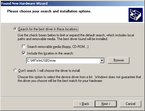
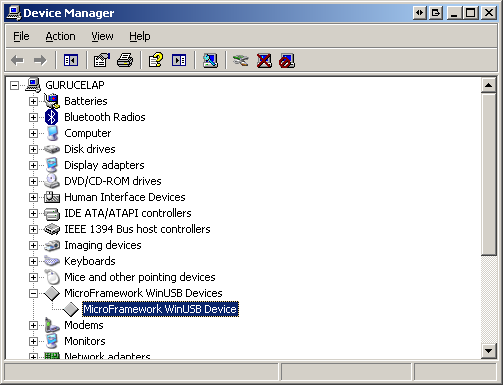
If you still have the "Found New Hardware Wizard" open you can now point the wizard to C:\MFWinUSBDriver and have it install the driver. If you don't have the wizard open anymore; go to the Device Manager, delete the unknown USB device from the "Other devices" node and re-attach (or reset) the TahoeII.


Now everything is ready and we can start the development of the PC application. Fortunately Jan Axelson already developed an application in C# that can talk to devices utilizing WinUSB. She provides full source code and it's a real good starting point for your own applications. Download the latest version from her WinUSB page.
Download and extract winusb_cs_xxx.zip to a folder of your choice and load the solution in Visual Studio 2008. Now open the frmMain.cs code and change the WINUSB_DEMO_GUID_STRING to match our inf file: "{77C99034-2428-424a-8130-DC481841429B}".
Now press F5 to run the solution. Enter some text in the "Bulk Transfers" textbox and click on the "Send" button:
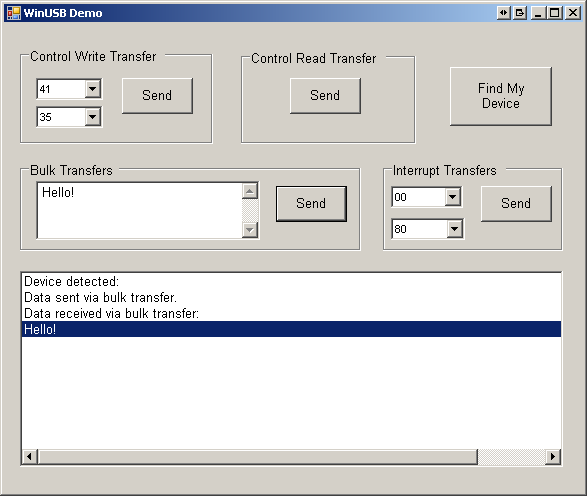
Eureka! The TahoeII is echoing back whatever we send to it. You can download the MicroFramework code and the MFWinUSB Driver here.
I'll try to follow up this article with an article showing how to setup the TahoeII as a USB Communication Device Class (CDC) so that you can communicate with your device without using WinUSB (and without having to sign your "driver").
Good luck in creating your next USB connected device running the MicroFramework!
Some portions of the text in this article were taken (and modified/updated/added to where necessary) from "How to Use WinUSB to Communicate with a USB Device".
Comments
string descriptors
Hello Michel, great article!
I wanted to ask - productName, friendlyName, displayName - which is used where and are there rules for any of them? (like no spaces in friendly name etc.)
Thanks!
RE: string descriptors
The string descriptors are used to make it easier for humans to identify the device (the computer uses VID/PID to identify the device). Strings in a string descriptor can use spaces and a length up to 255 bytes (since the length field in the string descriptor is a byte) which translates into 127 characters (because the string is UNICODE).
Thanks for reply, but where
Thanks for reply, but where do humans see these 3 strings? What's the difference between displayName and friendlyName? That's what I'm trying to figure out...
RE: Thanks for reply, but where
Those string descriptors can be read by the host driver and used to make it more clear what the device is. On Win32 the strings from the INF have precedence over the strings from the device itself. If you omit the strings in the INF (ProviderName, DeviceDesc) then the OS will query and use the strings from the device. You can see the strings in action in the Device Manager. You can query the strings from the INF or the device yourself by using the Setup API. As far as I can see the FriendlyName string is not used on Win32. On Windows CE there are no "inf" files, so Windows CE would use the string descriptors directly from the device.
Pingback
Few quick questions: where is
Few quick questions: where is WinUSB.dll located and how does Jan's project know where to find it?
RE: Few quick questions
WinUSB.dll is in C:\WINDOWS\system32 and that folder is in the path.
Thanks! Really useful post.
Thanks! Really useful post.
Winusb speed
what transfer speed can you achieve with winusb driver. is it better from a usb to serial communication at TTL level?
Thanks in advance
RE: Winusb speed
I have no data to say anything useful about this, sorry.
USBizi
This is a very usefull post, but a have a few questions to adapt it to my application: How can I do this comunication on the USBizi? Witch way should I debug it? WinUSB is the only way to conect the development board as a device?
RE: USBizi
This should work all the same. It's the MicroFramework and USB, both work (almost) exactly the same over different hardware (that's the beauty of it). Ask GHI Electronics if you have specific questions dealing with the USBizi hardware.
Hi, thanks for the useful
Hi,
thanks for the useful post.
Like the other, I have an question:
I've used this way to communicate with my device, but there are any ways to debug over Ethernet?
Thanks.
RE: Hi
If you are using the Tahoe then you can set that board to debug over Ethernet or serial. It's explained in the text above, but I'll repeat it here for you:
Setting the TahoeII to use Ethernet or serial debugging is easy; just hold SW4 while resetting the device for debugging over Ethernet, or hold SW2 for debugging over serial. If you set it to debug over Ethernet then don't forget to configure the TahoeII's Ethernet settings using MFDeploy (see "Configuring Ethernet on the Tahoe-II" in the TahoeII SDK documentation -> press F1 in Visual Studio)
Yes thank you, sorry I asked
Yes thank you, sorry I asked not right. The transport to the TahoeII board works fine. But I want to debug just in time the solution on my board like an solution on my PC. I want press 'F5' and work with breakpoints. But if I press 'F5' to debug my device-solution Visual Studio deploys right, and give me the output: The thread … ends with the code 0 (0x0). Understand you what I meant?
RE: Ethernet debug
That should just work, also over Ethernet. Are you building a debug version?
Yes I build a debug version.
Yes I build a debug version. And my device display shows on black in green:
Build Date:
Dec 2 2009
10:35:54
CPS = 0x200000df
PC = 0x1004d8b0
lr = 0x1004d8b4
SP = 0x08681520
Pingback
USB driver for TahoeII
Hi Michel
I have tried to follow your instructions for building the inf and catalog file, but failed miserably. I am using Windows 7 and the controller files in the WDK have been updated but that didn't seem to affect the Inf2cat.exe from building the catalogue file, no warnings and no errors. But on trying to install the the driver Windows informed me that the device had failed with Error(43) and the device driver had not been installed.
It installed the winusb.dll and wincoinstaller2.dll to the system32 but that's it.
What am i missing, I've obviously done something wrong, but have no idea what it is, do you have any advice? I am going to try and use the files you supplied for download and will let you know if the problem is with the Tahoe II or my building of the drivers.
By the way good article.
all the best
Erwin
RE: USB driver for TahoeII
Hi Erwin,
AFAIK, Windows 7 does not allow non-signed drivers to load anymore, so that is probably the problem. Try the drivers in the ZIP and let me know how you get on. If the drivers in the ZIP also don't work I'll repeat the instructions here on Windows 7 and will update the blog item where needed.
Zipped drivers
Hi Michel,
Thank's for the prompt reply, I have tried the zipped drivers and get the same response from Windows 7(driver failed to load Error 43). I was just about to try it on an XP machine, but That would be great if you could update your blog for Windows 7, as most of my work is on windows 7.
all the best
Erwin
Windows 7
Hi Michel,
The board install without a problem on windows XP, I would be grateful for you help/advice for installing on Windows 7.
All the best
erwin
USB CDC Communication to Microcontroller
Hi
First, Thanks for your nice comments and explanation.
I have a simple and special question:
As I understood in your project, you can communicate with another device via USB. So you implemented also a firmware or driver which connect your device to your application.
In my project I have a programmed Printed Circuit Board(PCB)and also a firmware (like a driver for a hardware) which already has installed on my laptop. Now, I can communicate with my programmed PCB via Tera Term (http://ttssh2.sourceforge.jp/) software.
I tried to just replace the VID and PID of my special PCB on your application to communicate with my PCB. But it did not work. The question is: which part of your project do I need change for communicating with my PCB? How can I use the installed driver (firmware) in your application?
Regards
Bamshad
RE: USB CDC Communication to Microcontroller
You need to change the WINUSB_DEMO_GUID_STRING string to correspond to the ClassGuid item in your inf file. Does the Win32 driver load correctly? Does your device show up in Device Manager without any exclamation mark?
Thanks Michel for your
Thanks Michel for your reply,
Yes, I installed the driver correctly and there is no exclamation mark in Device Manager. Now, I can communicate with my device via Tera Term.
Unfortunately I couldn't find any GUID in entire of "MFConsoleApplication1" solution. Would you please guide me more?
in "MFWinUSB.inf" file also there are two GUID which named : ClassGuid and DeviceInterfaceGUIDs. Should I change them also?
Cheers
Bamshad
Discard my last comment, I
Discard my last comment,
I downloaded the "winusb_cs_181" project and changed the "WINUSB_DEMO_GUID_STRING" to my ClassGUID. But again I couldn't find my device.
I should mention I have two different inf file and therefore I have two ClassGUID. I tested with both of them and I couldn't find my PCB. appreciate any idea which help me?
Thanks again
Bamshad
RE: Discard my last comment, I
Hold on... You're using CDC descriptors? Then WINUSB will not work. If you can communicate with your device over TeraTerm then CDC is working correctly. All you have to do now is write an application that opens the COM port you are opening in TeraTerm and do whatever you need:
HANDLE hCOM = CreateFile(_T("COM7:"), ...
DCB dcb;
dcb.Baud = 115200
dcb.Parity = ... etc
SetCommState(hCOM, &dcb);
WriteFile(hCOM, L"some string", ...)
char szBuffer[1000];
ReadFile(hCOM, szBuffer, ...)
Note the above is pseudo code of course!
Thanks for your reply. I
Thanks for your reply.
I think I misunderstood the difference between CDC and HID. As you mentioned I can connect to my device via port, so I need CDC. and the WINUsb is HID and if I want to use that I need to write a driver (or firmware) and install that on my computer, then with winusb or any other host application I can connect to my device. Right?
Thanks again
Bamshad
RE: Thanks for your reply. I
I think you do not fully understand WinUSB and you would need to read the linked documents that describe WinUSB. CDC and HID are device classes that already have drivers in Windows. If you create USB descriptors following the HID or CDC classification, then Windows will load those drivers when your device connects. If your device could not use CDC or HID (or you don't want to use those classes) then you used to have to write your own kernel mode driver. With WinUSB this is not necessary anymore. WinUSB simplifies access to your device by using a standard kernel mode driver with which you can communicate from user mode. If you want to use WinUSB then implement the descriptors as described in the blog post and use the INF above as base for creating your own "driver".
Thanks for everything, I
Thanks for everything, I think I get your point. The question is whats the difference between CDC and HID? and what is the difference (advantage/dissadvantage) between connecting your device via PORT and via ClassGUID?
RE: Thanks for everything, I
CDC exposes your device as a serial port over which you can communicate. HID is a class designed for human interface devices, and is abused sometimes for other simple communication because the descriptors are simple. If your device is not some sort of human interface device (like a mouse, keyboard, fingerprint scanner, etc) then you should NOT use the HID class. CDC makes it easy to communicate with your device over serial, and this may work for your device. It's your decision, you know what kind of device you are creating and what suits best. CDC or WinUSB, it's up to you.
Thanks for nice explanation
Thanks for nice explanation ;)
update the device's USB descriptors
Hi Michel,
Thanks for the article once again, managed to get everything up and running this time.
Did you manage to produce the article update showing how to setup the usb descriptors in a way that would allow communication and debugging at the same time. I would be very grateful for any information have on this subject.
all the best
erwin
RE: update the device's USB descriptors
Hi Erwin,
I can't remember ever saying I would update the article for that. In fact, I'm not even sure that will be possible. The HAL is responsible for the debugging communication with VS, so in order to combine that functionality with communicating with a .NET MF application over USB you'd have to combine the USB descriptors and your application descriptors in the HAL. The HAL then needs to "forward" all comms over your application interface to your application, while maintaining debug communications. Not an easy task I'd think (and you need the full port sources).